Your cart is currently empty!

MD800 Ethercat communication guide for Twincat 3
The SI-ECAT card is an EtherCAT fieldbus adapter card, which can be used in the ultra-high speed I/O network.
The protocol is applicable on the I/O layer.
This card features high efficiency, flexible topology, and easy operation. It is installed in the MD800 series AC
drive to increase the communication efficiency and implement the AC drive networking function, which
enables the AC drive to be a slave controlled by the field bus master station.
SI-ECAT accepts the fieldbus master station control. EtherCAT communication supports a minimum
synchronization cycle of 500µs. The internal bus between SI-ECAT, rectifier and inverter units have a
communication cycle of 40ms.
NOTE The SI-ECAT supports the CiA402 Velocity and Cyclic Synchronous Velocity (CSV) modes which are
suitable for the MD800 open loop (sensorless) operation. MD800 does not support encoder feedback.
INSTALLING THE SI-ECAT CARD
The SI-ECAT card is designed to be used as an expansion card embedded in the MD800 series drive. The SI-ECAT
expansion card is located on the rectifier module.

HARDWARE LAYOUT

The SI-ECAT card uses a standard Ethernet RJ45 socket, which is connected to the EtherCAT master station, and
its pin signal definition is the same as that of the standard Ethernet.
The pins of the network are the same, cross-wire and straight-wire are both possible.
SI-ECAT card terminal function description:
| Terminal symbol |
Terminal name | Description |
|---|---|---|
| EC IN | Input port | After installation, EC IN is on the left and EC OUT is on the right when facing to the RJ45 interface. The two interfaces must be connected correctly. The Cat5e shielded twisted pair (STP) network cable must be used for ensuring stability. To improve the anti‑interference capability of communication, it is recommended to install it in the expansion card slot 2. |
| EC OUT | Output port |
NETWORK TOPOLOGY
The AC drive supports EtherCAT bus. It adopts the standard RJ45 network port and standard connector. The Cat
5e shielded twisted pair cable with iron shell injection molding must be used to connect with the Ethernet
master station properly. With relevant communication setting, the communication with the EtherCAT master
station can be realized, thus realizing the networking function of the AC drive.
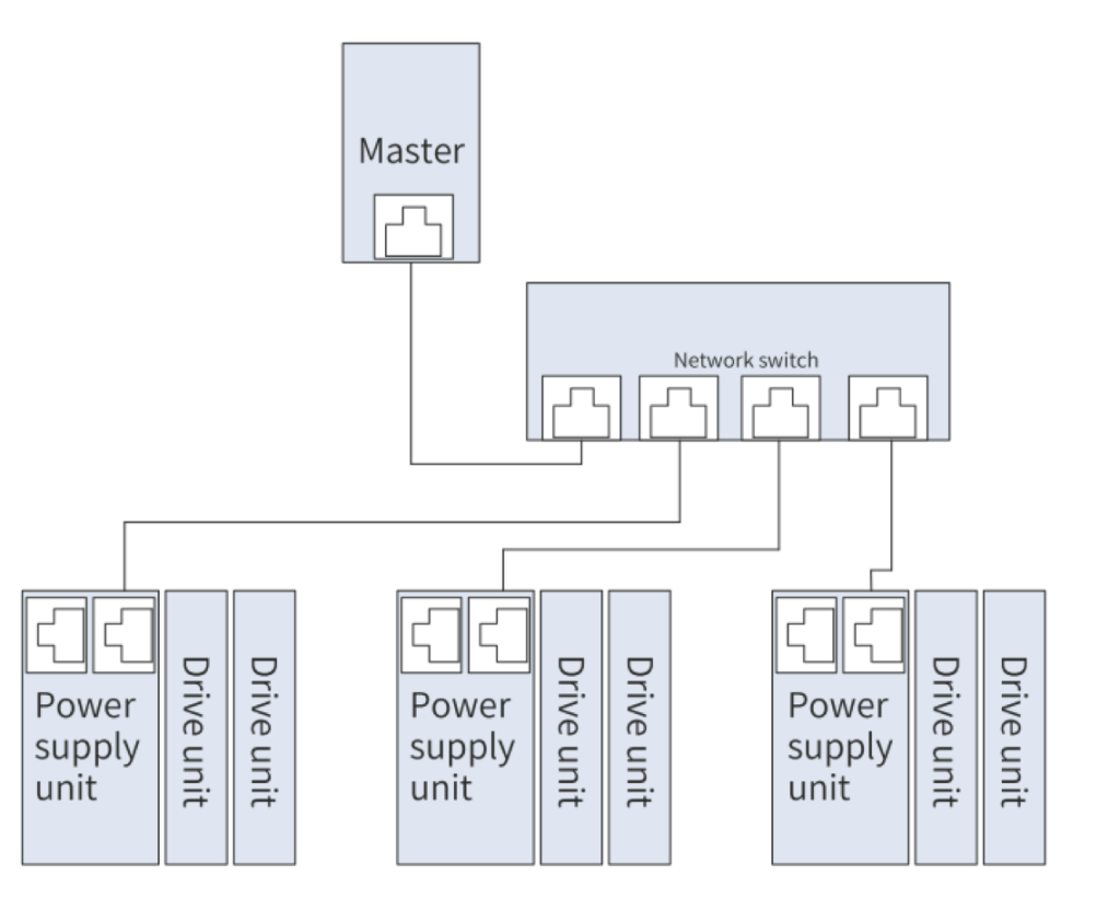
The topological structures supported by EtherCAT include bus, star, and tree topologies. Various networking
can be realized by using switches correctly.
Bus topology:

Star topology:
NOTE For this type of topology it is necessary to use a special switch such as the Inovance’s GR10-EC-6SW 6-
Port EtherCAT Branch Module.
QUICK START COMMISSIONING
After installing the SI-ECAT card on the MD800 series AC drive, complete configuration to enable the
communication between them.
The following parameters must be set to enable normal communication between the SI-ECAT card and MD800
series AC drive and connect the SI-ECAT card to the EtherCAT fieldbus network.
The table also shows the basic configuration of the single axis motor map and the different autotune modes.
For a more detailed description of the autotune process, consult the MD800 commissioning manual.
| Parameter | Description | Setting Range | Value |
|---|---|---|---|
| Rectifier communication | |||
| FD-10 | Communication protocol selection | 1:CANopen 2:CANlink 3:Optional communications card |
3 |
| Inverter communication | |||
| F0-02 | Command source selection | 0: External LCD panel/Commissioning software 1: Terminal I/O control 2: Communication control |
2 |
| F0-03 | Main frequency source selection | 0: Digital setting (initial value F0-08 can be modified by terminal UP/DOWN, non-retentive at power failure) 1: Digital setting (initial value F0-08 can be modified by terminal UP/DOWN, retentive at power failure) 2: AI1 3: AI2 4: (Reserved) 5: Pulse reference (DIO1) 6: Multi-reference 7: Simple PLC 8: PID 9: Communication setting 10: Synchronization control |
9 |
BECKHOFF’S CONTROLLER
Beckhoff’s TwinCAT master station is used as an example to describe the configuration of the SI-ECAT card.
NOTE : The 100M Ethernet network adapter with Intel chip must be used. Other network adapters may not
support EtherCAT.
- Install TwinCAT.
Windows XP system: tcat_2110_2230 is recommended.
Windows 7 32-bit system: tcat_2110_2248 is recommended. - Copy the EtherCAT configuration file (MD800_9Axis_V0.18.xml) of MD800 to the
TwinCAT installation directory.
TwinCAT2 directory: TwinCAT\IO\EtherCAT
TwinCAT3 directory: TwinCAT\3.1\config\IO\EtherCAT
TwinCAT3 is used as an example in the following section. The operation steps for TwinCAT2 are
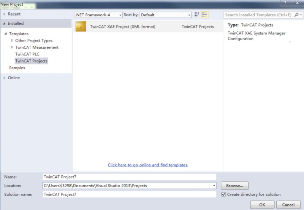
similar. - Start TwinCAT.
Click New Project to create a project.

Select TwinCAT XAE Project and click OK.
Install the TwinCAT network adapter driver.

Choose TWINCAT > Show Real Time Ethernet Compatible Devices…. In the displayed dialog box, select the
local network adapter in Incompatible devices, and click Install. After installation, the installed network
adapter is displayed in Installed and ready to use devices.

Search for devices.
Create a project, right-click Device, and then click Scan to search for devices, as shown in the
following figure.

The following message appears. Click OK.

Select EtherCAT device and click OK.

Click Yes.

Select NC configuration and click OK.

Click No.

Now the equipment search is complete, as shown in the following figure:

Configure TPDO:
1) Open drive configuration
2) Open “Process Data” tab
3) Select “Inputs”
4) Select 0x1A01, 0x1A02, 0x1A03, etc. to enable axis 1, axis 2, axis 3, etc. PDO inputs.
5) Select the corresponding index to configure the PDOs
6) The first two items are set to TPDO by default and cannot be changed. Right click at the
position indicated by step 6 in the following figure to add the TPDO mapping as required.
Each drive or the rectifier has a specific index:
- 0x1A01 Drive 1
- 0x1A02 Drive 2
- 0x1A03 Drive 3
- 0x1A04 Drive 4
- 0x1A05 Drive 5
- 0x1A06 Drive 6
- 0x1A07 Drive 7
- 0x1A08 Drive 8
- 0x1A10 Rectifier

Configure RPDO:
1) Open drive configuration
2) Open “Process Data” tab
3) Select “Outputs”
4) Select 0x1601, 0x1602, 0x1603, etc. to enable axis 1, axis 2, axis 3, etc. PDO outputs.
5) Select the corresponding index to configure the PDOs
6) The first two items are set to RPDO by default and cannot be changed. Right click at the
position indicated by step 6 in the following figure to add the RPDO mapping as required.
Each drive has a specific index:
- 0x1601 Drive 1
- 0x1602 Drive 2
- 0x1603 Drive 3
- 0x1604 Drive 4
- 0x1605 Drive 5
- 0x1606 Drive 6
- 0x1607 Drive 7
- 0x1608 Drive 8

View the SDO data list.
After the OP state is activated, you can view real-time data in the SDO data list or double-click the object
dictionary to modify the SDO data.

Activate the configuration and switch over to the running mode.
Click Activate configuration button:

The following dialog box is displayed:

Click OK.

Click OK to enter the OP state.

Control the AC drive through PDO.
Write corresponding values through the configured RPDO to control the AC drive.
