Your cart is currently empty!

MD800 Profinet communication guide for TiaPortal
The SI‐PN communication expansion card can implement data exchange among up to nine CANopen nodes, including one rectifier and eight inverters.
The SI‐PN communication expansion card complies with IEC61158‐5‐10 and IEC61158‐6‐10 application layer standards, the international PROFINET Ethernet standards.
This card is to be installed on the MD800 series AC drive. The AC drive converts the PROFINET protocol to the CANopen protocol, making the AC drive into a fieldbus slave controlled by the fieldbus master.
INSTALLING THE SI-PN CARD
The SI-PN card is designed to be used as an expansion card embedded in the MD800 series drive. The SI-PN
expansion card is located on the rectifier module.

HARDWARE LAYOUT
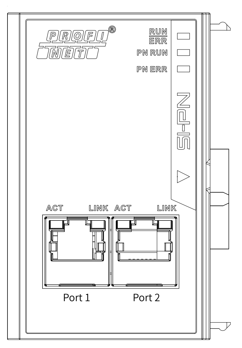
The SI‐PN communication expansion card uses a standard Ethernet RJ45 socket to
connect to a PROFINET master. Its pin assignment aligns with standard Ethernet pins, allowing for the use of both crossover and straight‐through cables.
SI-PN card terminal function description:
| Terminal symbol |
Terminal name | Description |
|---|---|---|
|
Port1 |
Network port 1 |
● After the card is installed, Port1 is on the left and Port2 is on the right when you view them facing the RJ45 interface. ● To ensure stability, it is recommended to use the Cat5e shielded twisted pair (STP) network cable. ● For enhanced communication interference resistance, it is recommended to install the card in expansion slot 2. |
|
Port2 |
Network port 2 |
NETWORK TOPOLOGY
After communication between the SI‐PN communication expansion card and the AC drive is implemented, connect the SI‐PN card to the PROFINET master and configure related parameters to enable communication between the SI‐PN card and the PROFINET master, implementing AC drive networking.
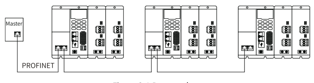
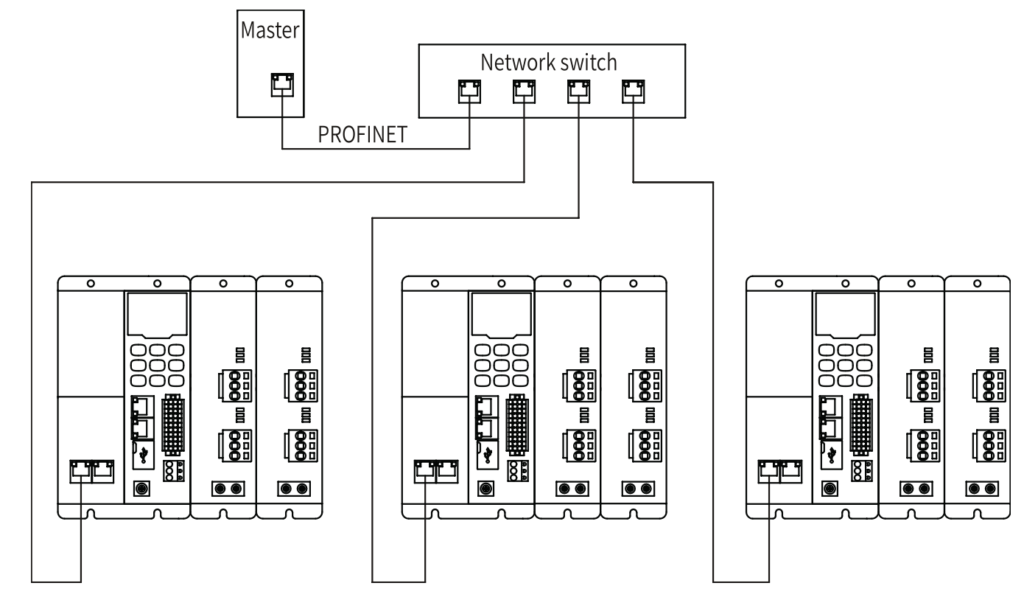
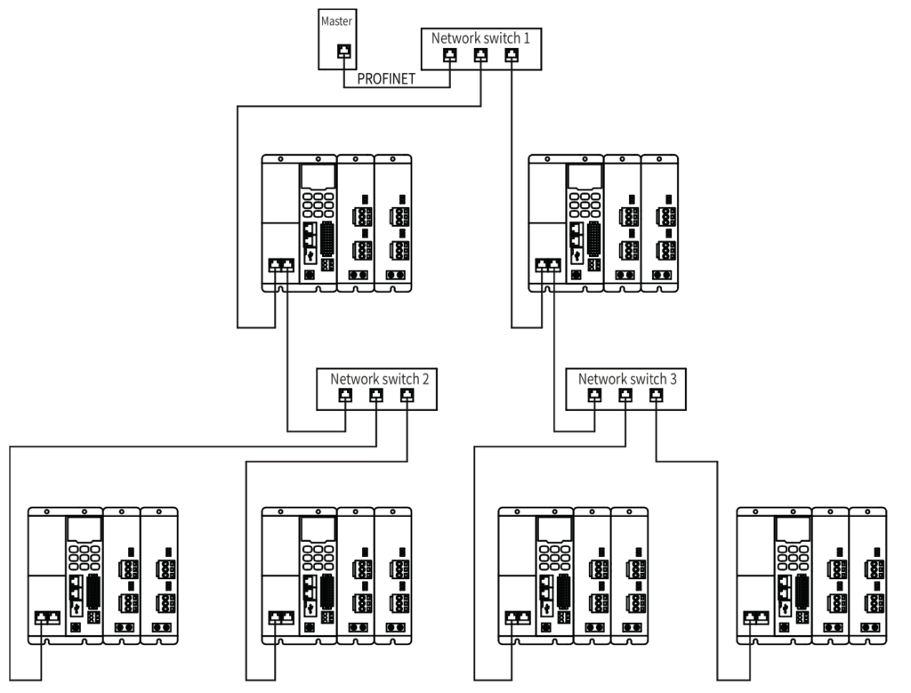
The PROFINET master supports bus, star, and tree topologies. Different networking modes can be implemented by using switches.
Bus topology:
Star topology:
Tree topology:
QUICK START COMMISSIONING
After installing the SI-PN card on the MD800 series AC drive, complete configuration to enable the
communication between them.
The following parameters must be set to enable normal communication between the SI-PN card and MD800
series AC drive and connect the SI-PN card to the Profinet fieldbus network.
The table also shows the basic configuration of the single axis motor map and the different autotune modes.
For a more detailed description of the autotune process, consult the MD800 commissioning manual.
| Parameter | Description | Setting Range | Value |
|---|---|---|---|
| Rectifier communication | |||
| FD-10 | Communication protocol selection | 1:CANopen 2:CANlink 3:Optional communications card |
3 |
| Inverter communication | |||
| F0-02 | Command source selection | 0: External LCD panel/Commissioning software 1: Terminal I/O control 2: Communication control |
2 |
| F0-03 | Main frequency source selection | 0: Digital setting (initial value F0-08 can be modified by terminal UP/DOWN, non-retentive at power failure) 1: Digital setting (initial value F0-08 can be modified by terminal UP/DOWN, retentive at power failure) 2: AI1 3: AI2 4: (Reserved) 5: Pulse reference (DIO1) 6: Multi-reference 7: Simple PLC 8: PID 9: Communication setting 10: Synchronization control |
9 |
TiaPortal example
Before using the PROFINET master, you need to configure the GSDML file of the slave to add the corresponding slave device to the system of the master. You can download the GSDML file here:
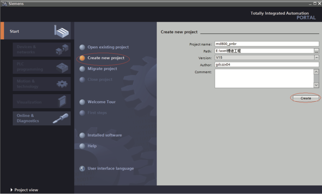
- Create a project.
a. Click “Create new project”, set “Project name” and “Path”, and click “Create”.
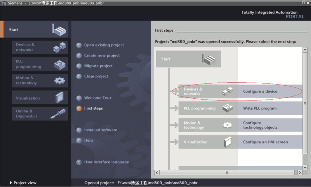
b. Click “Configure a device”, as shown in the following figure.
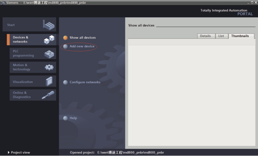
c. Click “Add new device”.
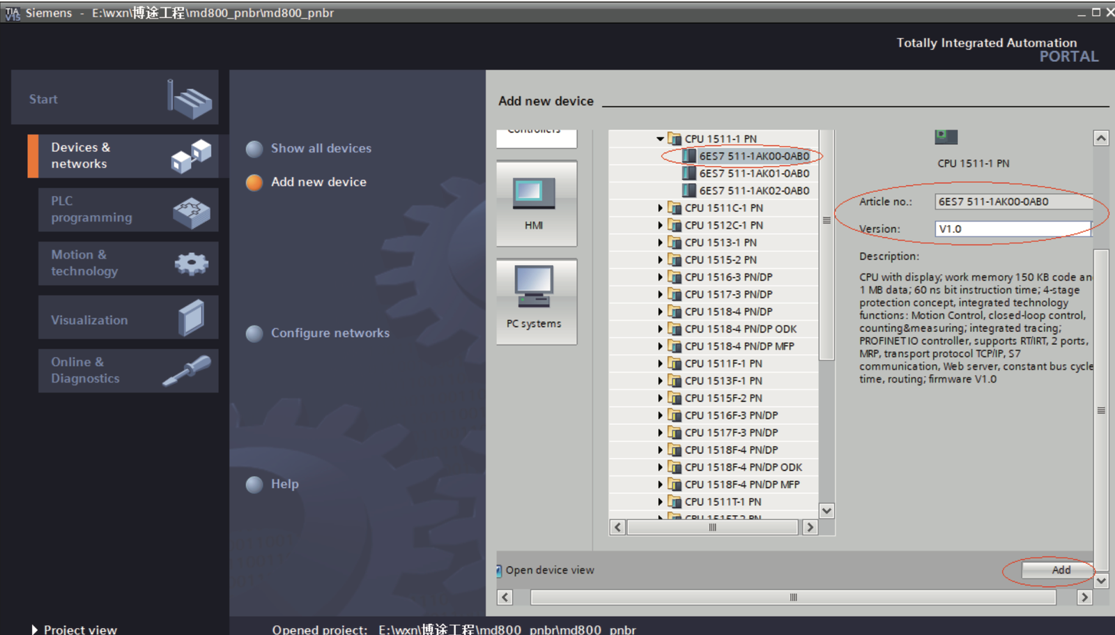
d. In the pop‐up window, select a PLC and its firmware version based on the order number. Click “Add” or directly double‐click the master. The master is established.
Note: When selecting the PLC, ensure the order number matches to avoid download failures.
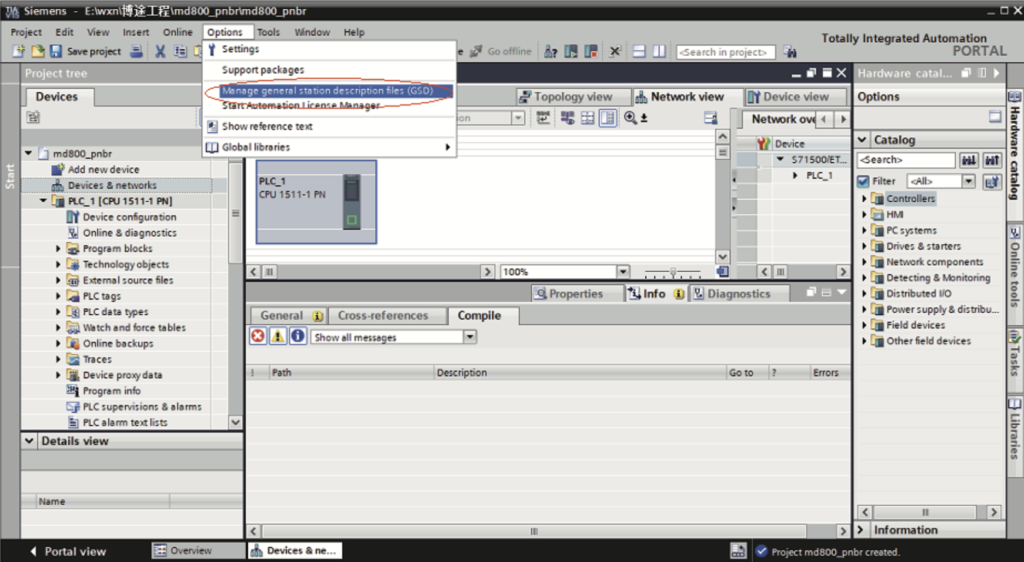
- 2. Install a GSD file (Skip this step if the GSDML file has been installed).
a. Choose “Options” > “Mange general station description files (GSD)”.
b. Select a path (which must not contain any Chinese character) for storing the GSDML file, select the GSDML file to be installed, and click “Install”.
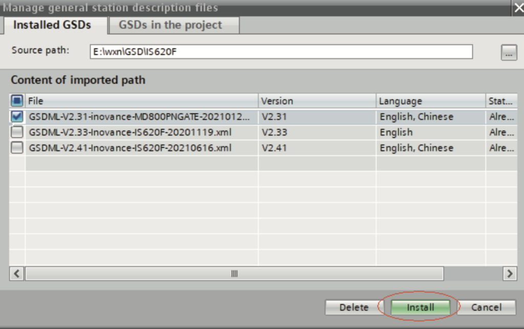
Wait until the installation is completed, and click “Close”.
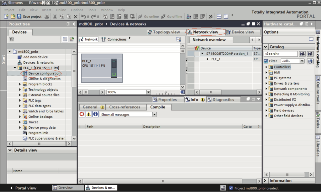
3. Establish a network.
a. Click “Device configuration”. Select “Network view”.
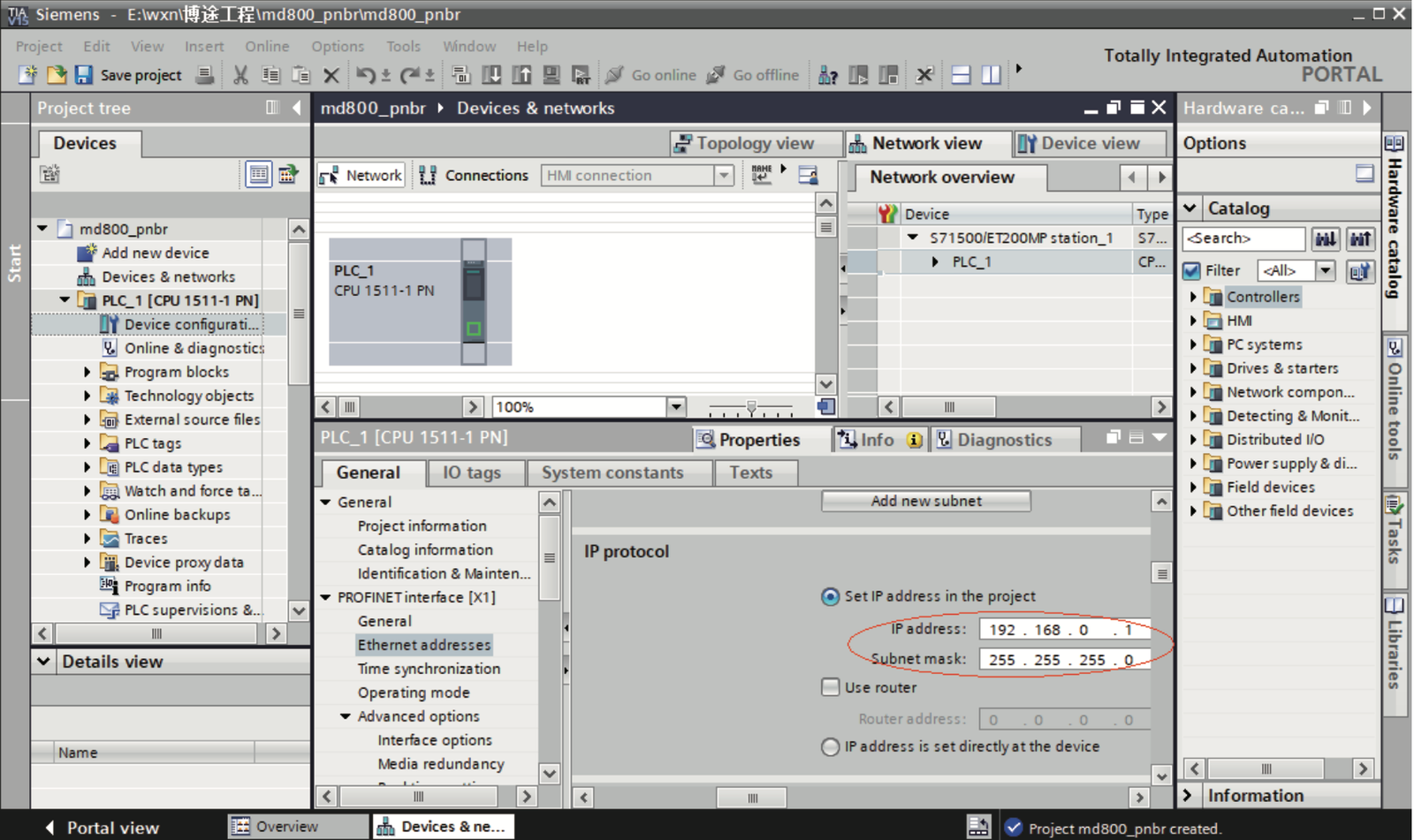
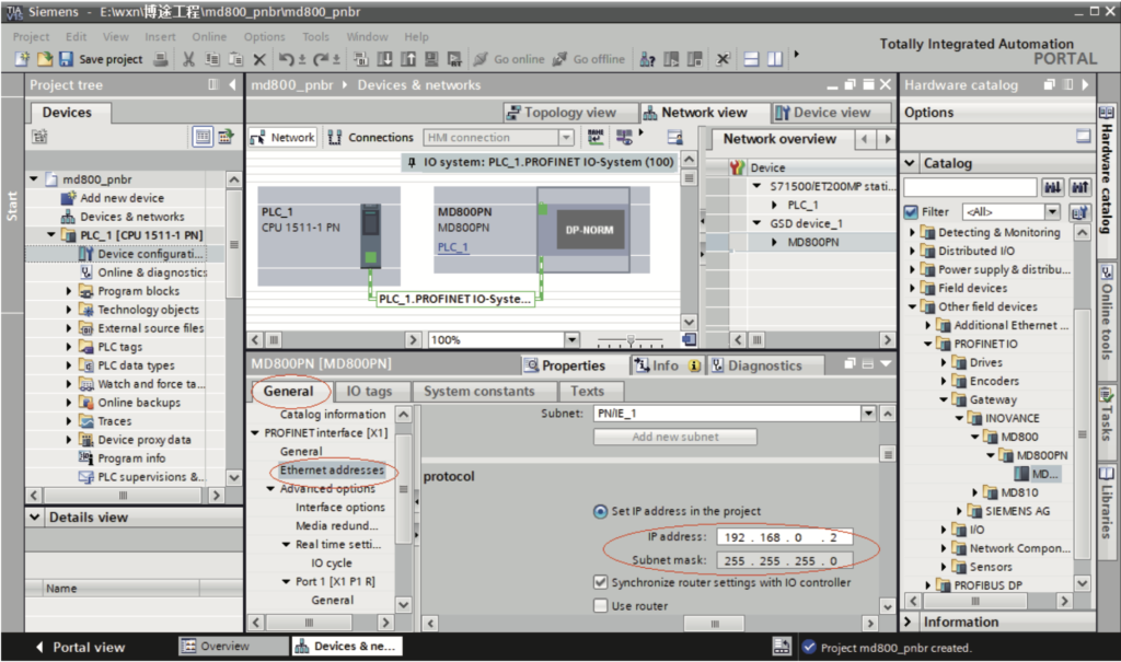
b. Select the Ethernet port of the PLC, choose “Properties” > “General”, and set the IP address and subnet mask of the PLC master station.
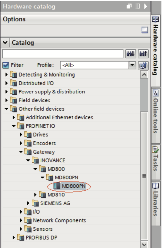
c. In the “Hardware catalog” on the right, navigate to “MD800” and double‐click “MD800PN”.
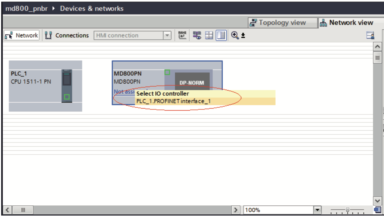
d. Click “Not assigned” and select a master system for the slave.
e. Select the slave, choose “Properties” > “General” > “PROFINET interface [X1]” > “Ethernet addresses”, and set the IP address.
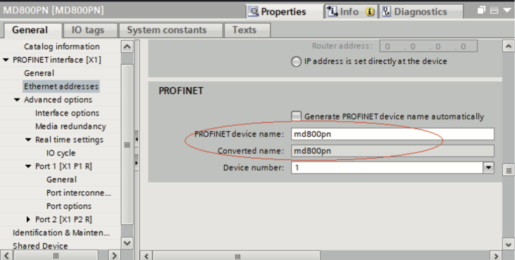
f. Scroll down the screen to the “PROFINET” section. Deselect “Generate PROFINET device name automatically” and enter a name in the “PROFINET device name” field. (Alternatively, you can keep the option selected to allow the system to generate a device name automatically.)
4. Configure a CANopen slave.
Note
Process of configuring the SI‐PN communication expansion card:
1. Double‐click or drag a rectifier or inverter from the module list to add a slave. 2. Configure mapping relations for the slave.
3. Configure process data for the slave.
To configure multiple inverters that have the same settings as an existing inverter, you can simply copy the inverter, without the need to repeat the process above.
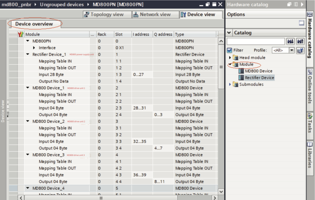
a. Add a slave:
Select a slave and switch to the “Device view”. Navigate to “Hardware catalog” >
“Module” and you can find two module options: “Rectifier Device” and “MD800 Device”. Double‐click a module to add it to the “Device overview” list.
Note
- ● The types and number of modules configured must match the devices in the actual network.
- ● For rectifiers, select “Rectifier Device”. Even if there is no process data for rectifiers, you must add a “Rectifier Device”.
- ● For inverters, select “MD800 Device”. “MD800 Device_1” corresponds to inverter 1, “MD800 Device_2” corresponds to inverter 2, and so on.
b. Configure mapping relations.
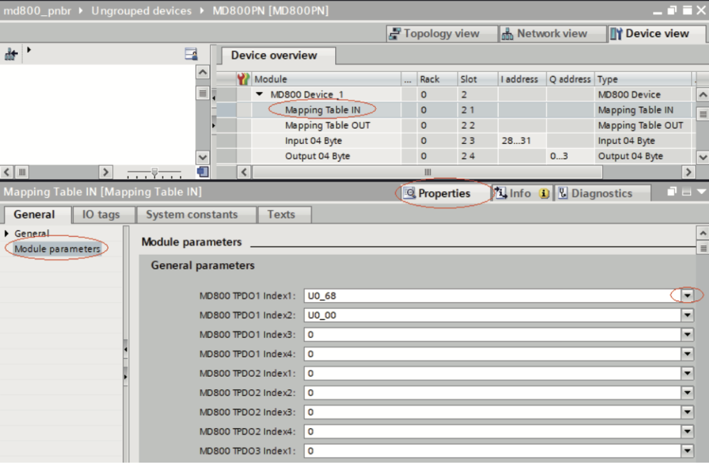
1). Select “Mapping Table IN”. Navigate to “Properties” > “General” > “Moduleparameters”. Set TPDO data mapping relations for the slave by using the drop‐down lists.
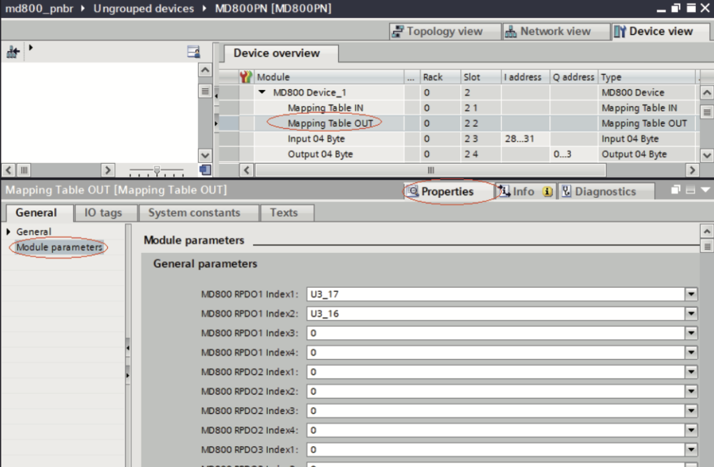
2). Select “Mapping Table OUT”. Navigate to “Properties” > “General” > “Module parameters”. Set RPDO data mapping relations for the slave by using the drop‐down lists.
Note
- ● Slot 1 (Mapping Table IN) corresponds to the mapping of TDPO data, which is data from the slave to the master. Slot 2 (Mapping Table OUT) corresponds to the mapping of RDPO data, which is data from the master to the slave.
- ● Each slave supports a maximum of four TPDOs and four RPDOs. The mapping relations for the same PDO need to be consecutive.
- ● For unused PDOs, the mapping relation defaults to 0.
- ● Each mapping relation corresponds to a 16‐bit parameter, representing twobytes of data.
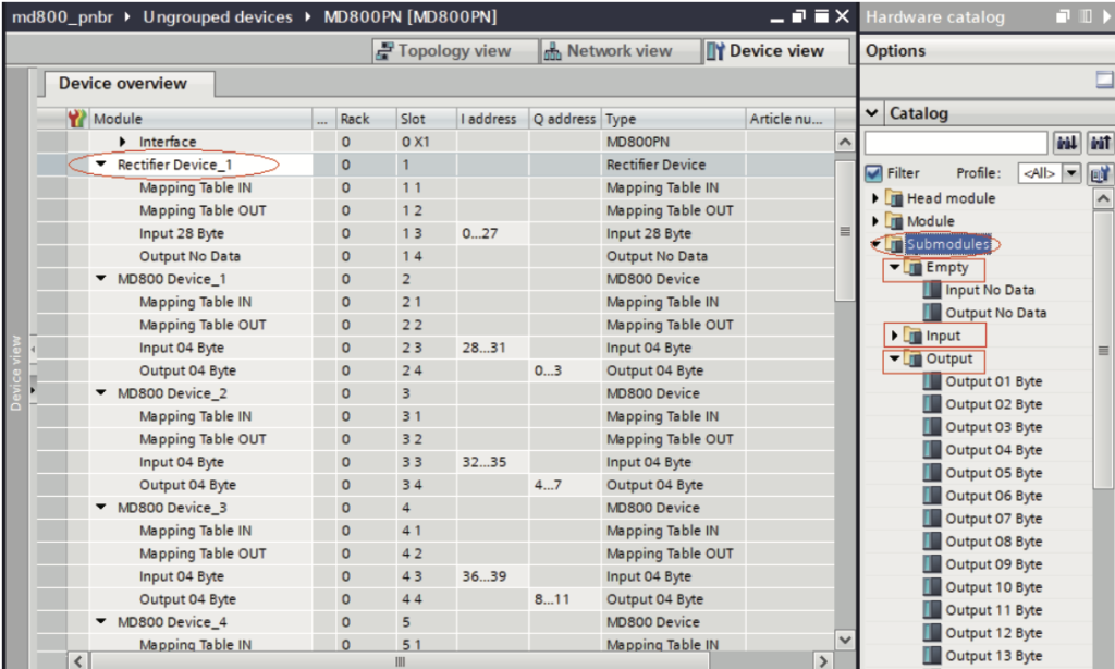
c. Configure process data.
Select the module in the “Device overview” list. Navigate to “Hardware catalog”> “Submodules” and you can find three directories: “Empty”, “Input”, and “Output”. They are used to set the process data lengths of the module. In the “Output” directory, set the length of process data from the master to the slave. In the “Input” directory, set the length of process data from the slave to the master. If any process data is not needed, add configurations in the “Empty” directory.
Note
- ● Slot 3 corresponds to Input data. The length of Input data must match the length of the mapping relations configured in Slot 1 (Mapping Table IN). Slot 4 corresponds to Output data. The length of Output data must match the length of the mapping relations configured in Slot 2 (Mapping Table OUT). For example, if there are five mapping relations configured in Mapping Table IN, insert “Input 10 Byte” in Slot 3. If there are seven mapping relations configured in Mapping Table OUT, insert “Output 14 Byte” in Slot 4.
- ● If a station does not have Input or Output data, insert “Input No Data” or “Output No Data” in the corresponding slot.
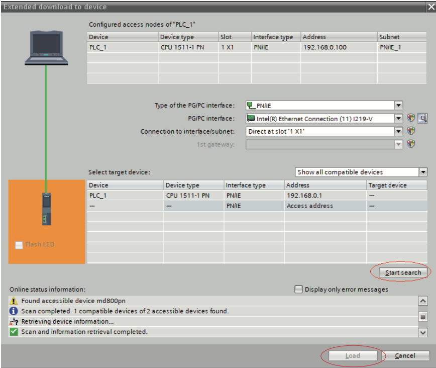
d. Load the project.
After the configuration is completed, save the project. Set the IP address of the PC to be in the same network segment as the PLC. (Avoid IP address conflicts with the slaves in the configuration. Alternatively, you can allow automatic IP address allocation for the PC.) Then, compile the configuration, click “Load”, select an interface, and click “Start search”.
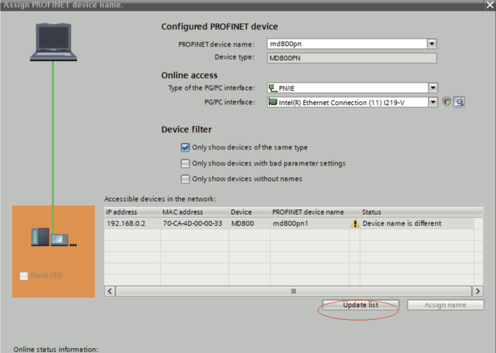
e. Assign a device name.
1). After the loading, you need to assign device names for slaves not named.
Select a slave, and choose “Online” > “Assign device name” (or right‐click the slave and choose “Assign device name” in the shortcut menu).
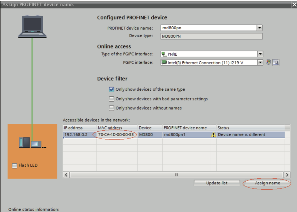
2). From the accessible nodes in the network, select the slave to be named (differentiate the slaves based on their MAC addresses), and click “Assign name”.
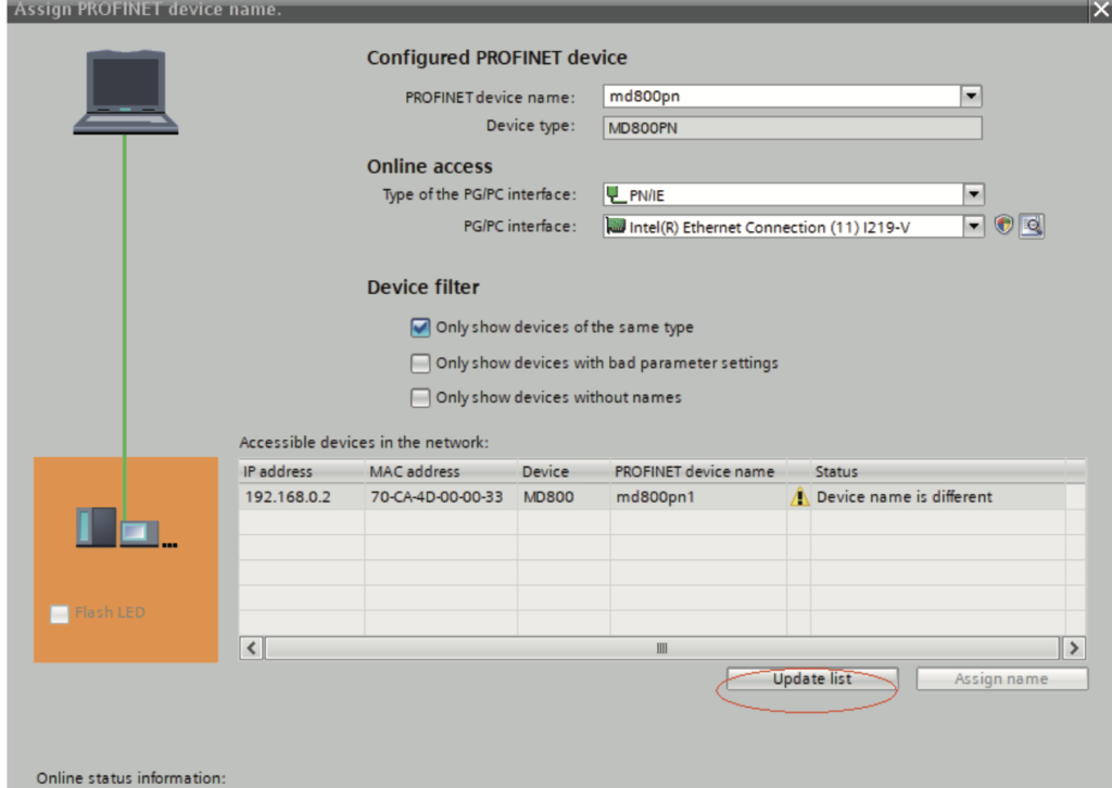
The following screen indicates successful device name writing. The displayed device name must be consistent with the name under “Configured PROFINET device” shown in the preceding figure. After assigning the device name, close the window or select another device from the “PROFINET device name” drop‐down list to assign names for other devices.
The slave will save the assigned name, and the master identifies each slave based on the device name. (The MAC address is not intuitive to use. The process of assigning a device name is actually binding the device name with the MAC address.)
Note
- ● Each device name can be assigned to only one slave in the network.
- ● After you modify a device name in the configuration, it is necessary to re‐assign the name.
- ● After you modify an IP address, you only need to load the modified configuration to the PLC for the modification to take effect. Name re‐ assignment is not required.
- ● Once all the preceding steps are completed, you can write programs in the PLC to control the AC drive.